Design of masonry arches
The verification of the load bearing capacity is performed by considering a
compression line set in the masonry. The compression line is by the user defined by the vertical placement of the supports
and the placement at the center. The arch is considered to be limited by a lower and an upper plane of limitation.
A vertical displacement equal to zero is assumed for archs in general. This leads to the optimistic assumption of E = ∞ in the surrounding construction. Cracks in archs is often related to this assumption (not fulfilled).
The planes of limitations are considered horizontal or parabolic-shaped,
geometrically designated by the camber of arch, length, etc.
The supports are considered to be placed on a vertical line at the faces of
support.
The pressure zone is a symmetrical zone around the compression line, where the overall width is twice the smallest distance from the line of pressure to the planes of limitation.
Positioning the compression line at the support and at the center is under normal circumstances done by iteration, minimizing the degree of utilization.
For both the shift and the hidden arch, the shear force capacity is verified by the supports. The contribution of friction from the horizontal reaction is taken into consideration.
With shift arch the bed joints are considered to be perpendicular to the lower plane of
limitation. The coefficient of utiliization in this case is defined as the
maximum value of:
σbedjoint/fd or
τbedjoint/(µd * σbedjoint + fvd0)
measured in any cross-section.
Where σbedjoint is the normal stress and τbedjoint is the shear strain.
With hidden arches, there are two cases: an arch supported throughout
horizontally, and an arch supported horizontally only by the two supports.
When the height of the arch by the supports is equal to the total height (τb
= h), the degree of utilization is defined as the maximum value:
σbedjoint/(0.5*fd) measured in any cross-section.
If the height of the arch is less than the total height (τb
< h), the degree of utilization is defined as the maximum value of:
σbedjoint/(0.5*fd) or
τbedjoint/(µd * σbedjoint + fvd0) measured in any cross-section.
For the purpose of indicating positions, etc, an xy-coordinate system is defined having origon at the left limit of the clear span, in the lower plane of limitation.
The modulus of elasticity is used to calculate the elastic deflection and the moment of lateral buckling. An accurate value is not crucial for the load bearing capacity.
The moment of lateral buckling is calculated for an arch without supports perpendicular to the plane of the arch, between the supports.
Shift or hidden arch
The arch is specified as a shift arch or a hidden arch. A hidden arch is defined as an arch with bed joints in the horizontal plane (i.e. ordinary masonry). A shift arch is defined as an arch where the bed joints are perpendicular to the lower plane of limitation.
Initial shear strength
The initial shear strength is the part of the shear strength not resulting from friction. The value is transferred automatically from the heading "Masonry".
The value can, of course, be overwritten in the current calculation.
Concentrated loads, masonry arches
The design value of the concentrated loads. Calculations are possible with an infinite number of concentrated load.
Compressive strength, fk
The value is transferred automatically from the heading "Masonry". The value can, of course, be overwritten in the current calculation.
Position of the compression line
The position of the compression line is always specified vertically. It is thus of no importance whether it is a shift or a hidden arch. The position is allways from the horizontal line at the top of the clearing.
Height of arch at endpoints
The height of the arch at the faces of support, eb.
When calculating a hidden arch, the vertical height is indicated.
When calculating a shift arch, the distance along the bed joint, starting in the corner between the vertical support
face, and the lower restraining plane, is indicated.
If eb is equal to the total height of a hidden arch, the arch is considered supported horizontally throughout the height. If eb is smaller than the total height, the hidden arch is considered to be supported horizontally at the supports only, and any horisontal cross section should be able to resist the horizontal stress component as the shear stress in the bed joint. The load bearing capacity is thus altered significantly when eb is less than the height, compared to eb being equal to the height.
The total height in the center
The total height of the arch in the center is specified. If a flexible damp proofing course is used, the height of the arch can only be measured to the damp proofing course.
Iteration or known position
If the positions of the compression line and the supports are known, the iteration is not used, and the actual position of the compression line is indicated.
By not using the iteration, the degree of utilization for the arch in question will be greater.
In certain cases, better results can be achieved by adjusting the position found by iteration slightly. For example, a symmetrical concentrated load won't always result in the same position of the right and left support because the concentrated load is included in a sub-element, which is not necessarily symmetrically positioned, and thus the calculated internal forces can be slightly asymmetrical. This won't have a great influence on the size of the reactions or the degree of utilization. In the case of symmetrical loads, however, by positioning the supports in the same height as the average between the ones found by iteration, uniform reactions can be achieved.
The speed of iteration/the accuracy can be changed by altering the guiding parameters. This should only be done when the user is well aquainted with the module and the contructions to be calculated. The iteration process can be shut off, if it is desirable to position the supports and the compression line manually.
Clear span
Design value of the span below the masonry arch.
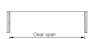
Figure 1. Clear span
Often equal to the projected width of the opening, but in cases with recessed joints deeper than 3 mm, the clear span should be increased by the joint depth on both sides.
It is recommended to control the dimensions of the arch and the placement of possible point loads for crude errors by using the function "Drawing".
Minimum amount of iterations
The iteration process stops, when one iteration improves the coefficient
of utilization less than 1%, depending on the amount of iterations and
the parameter of accuracy.
To avoid the calculation stopping at false optimum, a number of iterations are
runned, without checking the impovement of the degree of utilization.
Minimum amount of turns
During the iteration process, the 3 points determining the compression line (two supports and the center)
are moved up and down. The direction is changed when the coefficient of
utilization increases instead of decreasing. The step length is decreased for every turn,
in order to calculate the optimal point as precisely as possible.
The parameter decides how many times the direction is to be changed, as a
minimum, during the optimization of the placement of the compression line.
Characteristic coefficient of friction µk
The friction, µk, is the part of the shear strength not resulting from the cohesion.
The value can for mortars with cement be set to 1,0. For lime mortars with no cement the value is 0,6. The value is transferred automatically from the heading "Masonry".The value can, of course, be overwritten in the current calculation.
Accuracy
The parameter defines the accuracy of iteration and thereby the time consumption.
A large number is equivalent to a large time consumption and a more accurate calculation.
In some cases, where the compression line is close to the planes of limitation, increasing
this parameter can give a better utilization of the arch.
Amount of subelements
The arch is divided into an amount of subelements with equal horizontal length.
More subelements usually means a more accurate result. The iteration process,
however, will be slower.
In some cases, when the line of pressure is close to
the planes of limitation, increasing this parameter can give a better
utilization of the arch.
Camber of arch
The camber is the vertical distance measured at the center of the arch between the lower plane of limitation, and the
horizontal line at the top of the clearing .
With shift arch the bedjoint is considered perpendicular to the lower plane of limitation of the arch.
When straight shift arch is used, it is thus necessary to indicate a
ficitive camber, unless the units are vertically alligned.
The lower plane of limitation is considered a parabola between the faces of
support and the camber. If the arch is a semi-cirkel, or a semi elipse, it might
be necessary to indicate a larger camber and/or a larger clear span compared to the actual
geometry.
If the "arch" is a triangular one, it is conservative to use the the actual camber.
Straight shift arch: The fictive camber (fp) for straight shift arch, is defined
as:
fp = (1/4) * (1/n) * the clear span,
where n is the gradient in relation to vertical of the unit at the face of
support.
n is typically 3 - 6. In cases where the units are vertical, n = ∞ and fp = 0.
Uniform load
The design value of the arch's uniform load can result from the dead load of the masonry in and above the beam, and from dead and live load on storey partitions.
Thickness
Rules in the N.A. for minimum thickness of walls shall be applied
No reduction is necessary for joint depths less than, or equal to, 3 mm. In cases of joint depths exceeding 3 mm, the thickness is reduced by the full joint depth.
Example:
If the masonry is constructed using units (150 mm) with a one-sided recessed joint, with a depth of 10 mm, the thickness will be: 150 mm - 10 mm = 140 mm.